What are oscilloscopes used for?
Can oscilloscopes measure current?
They can! The most common way for automotive diagnostics is with a non-contact ammeter.
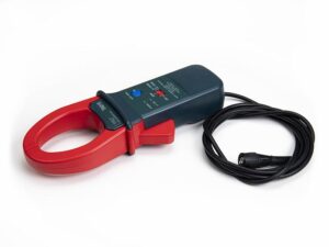
As we know, a magnetic field is generated around a conductor which carries current.
A non-contact ammeter detects the intensity of the magnetic field around the conductor being measured. The non-contact ammeter generates a voltage proportional to the detected magnetic field and transmits it to the oscilloscope.
What are the basic functions of an oscilloscope?
Sampling rate
Sampling rate is the number of measurements taken in a predetermined (by the user) time interval.For example, taking 10,000 readings in 50msec, would result in a sampling rate of 200,000 per second (1 second / 50ms, or 1s / 0.05s = 20 times, so 20 x 10,000 = 200k Samples)
Triggering
Triggers on oscilloscopes allow us to capture a stable waveform even with complex signals.They are set in such a way to capture a specific voltage threshold. Once the threshold is met or triggered, the waveform is plotted from that point onwards.
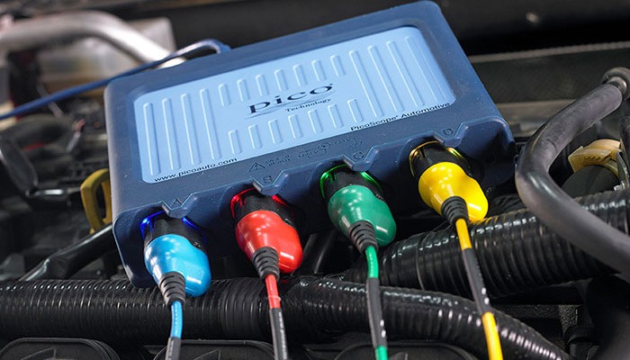
What is a USB oscilloscope?
A USB oscilloscope connects to a computer and needs a specific software to send the measurements to.
The Software plots the measurements as points in the display area and connects them with a line to form a waveform.
An oscilloscope is an essential tool for automotive diagnostics
Engines and vehicle systems become more and more complex. The ECUs work faster, they receive more signals from sensors and control more actuators.
The complex calculations they perform need accurate sensor signal or actuator feedback readings, otherwise fault codes may appear.
To troubleshoot those faults, we can of course use Multimeters! Multimeters are good tools for basic measurements, but how could you use one to detect cylinder compression problems, or an injector performing badly? Their slow sampling rate makes them good only for basic troubleshooting tasks, like simple DC or AC voltage measurements.
Let’s apply the use of an oscilloscope in a couple of scenarios.
Compare the two hypothetical troubleshooting actions performed by two different technicians:
Fault: Suspected low compression on a four cylinder common rail diesel engine.
Technician 1 approach:
- Depressurise common rail system
- Remove injector and high pressure line (contamination risk)
- Block common rail outlet for that injector (contamination risk & injury risk if the wrong block-off tool is used)
- Connect pressure gauge
- Disable engine starting
- Crank engine and record cylinder pressure
- Remove compression tester and block-off tool
- Refit injector and high pressure line
- Repeat steps 2-7 for the other injectors
- Compare results and find faulty cylinder.
Technician 1: Time required = 2 hours
Technician 2 approach:
- Connect non-contact ammeter to starter motor Bat+
- Connect voltage probe to camshaft sensor signal
- Disable engine starting
- Crank engine
- Record current waveform
- Identify cylinder No.1 on the current waveform by matching it with the reference point on the camshaft sensor signal
- Find the cylinder with the lowest current peak. By knowing the firing sequence, the cylinder number can easily be found.
Technician 2: Time required = 30mins or less and no fuel system contamination risk.
Fault: Possible injector problems (electrical)
Simply capture a waveform of each injector and compare it with the rest. The one that looks different indicates the failed injector!
My recommendations for automotive USB oscilloscopes:
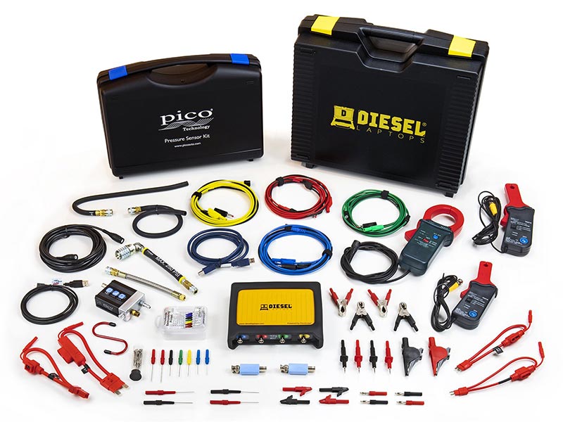
This is a list of three kits containing the same 4-channel oscilloscope, but with different cable and ammeter options to suit all budgets. Just add a laptop!
Standard Oscilloscope Kit (extra current clamp and fuse extension leads to measure current)
Advanced Oscilloscope Kit (same as standard kit plus an extra current clamp, WPS500X Pressure Transducer and some other goodies! – that’s the one I am using!)
Have a look at my other post too!: My diagnostic tool suggestions.