A standardized, structured procedure is the key to any Fault Code troubleshooting
How is a Fault Code generated?
Which System is responsible to determine if a Fault Code needs to be shown?
The main decision-maker is always a Control Module – this could be the ECM, a CAN-Bus Module (eg. NOx Sensor module), or in other words, a small computer.
But guess what!
A computer always works with a structured approach to any procedure it is assigned to carry out. If we manage to understand the software logic behind Fault Codes, then nothing stands in the way in efficiently diagnosing any Sensor fault.
A Control Module is simply a Comparator
The Control Module must compare values to determine how to perform a certain task. Let’s analyze the logic by looking at this example:
Task: Measure engine oil pressure.
Specifications: 2,0 V or below indicates low oil pressure (this value is only an example!)
The ECM is programmed to expect a signal voltage from the oil pressure sensor, which must be equal or higher than 0,5 V and equal or lower than 4,5 V.
So it COMPARES the measured voltage to the pre-determined values given by the module’s programmer.
It also converts the signal value to a pressure value for the vehicle’s display, or switch on the low oil pressure warning if the signal value is lower than a certain value.
Here’s the Computer logic in steps:
- Measure oil pressure signal
- Is the signal acceptable? (between 0,5 V and 4,5 V)
- If “YES”, then continue to step 4. If “NO”, continue to step 6.
- If the signal is equal or higher than 2,0 V, go back to step 1. Otherwise continue to step 5.
- If the signal is below 2,0 V, then switch on the Low Oil Pressure warning on the dashboard and then go to step 1.
- If the signal is below 0,5 V, show Fault Code 123 (example) and continue to step 1. Otherwise go to step 7.
- If the signal is above 4,5 V, show Fault Code 124 (example) and continue to step 1.
The Control Module follows the steps described above, in a sequence which always starts from Step 1. There can be no deviation from this, otherwise the controller would not know what to do…
How is a fault code generated?
Look at this Example:
Cummins QSB6,7 Fault Code: 1844
Fault Description: Crankcase Pressure Circuit – Voltage Below Normal or Shorted to Low Source
(Note the word Circuit!)
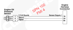
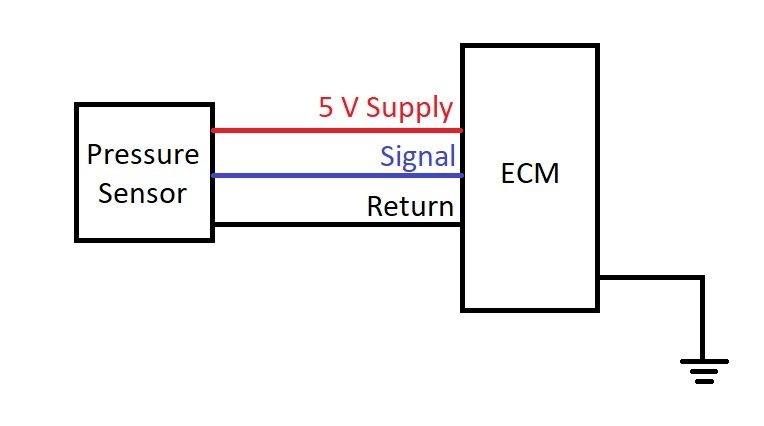
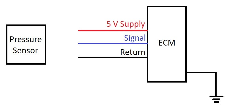
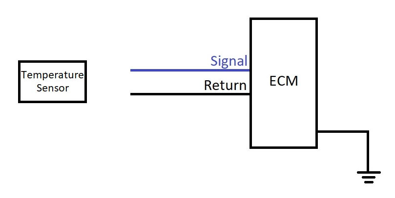
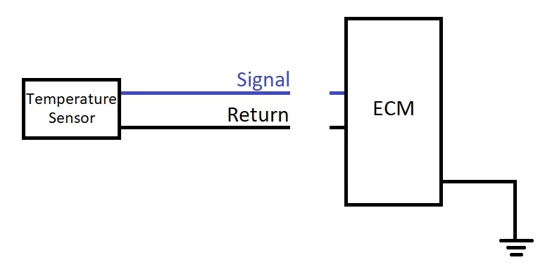
ALWAYS approach the fault as a circuit problem, rather than a sensor problem. Each sensor is connected to a circuit made of 3 parts: the ECM, Wires (cable harness) and the Sensor itself.
For this specific pressure sensor, there must be a voltage supply, a signal wire and a return wire to complete the ground through the ECM.
Let’s think about it – what are the reasons for this fault code?
Since the description contains “Voltage Below Normal”, we will assume the signal voltage arriving at the ECM is zero Volts (0 V).
What could have happened to cause the measured signal to be Zero Volts?
1st Possibility: Broken Supply wire, so the sensor cannot generate a signal.
2nd Possibility: The Return wire is broken, which prevents the sensor from getting supply voltage and in turn, generating a signal.
3rd Possibility: The Sensor is broken internally, so it does not generate a signal at all.
4th Possibility: Signal wire broken / open circuit.
5th Possibility: Bad contact on any of the sensor pins (loose connection, bent or broken pin).
6th Possibility: Internal ECM problem (No supply voltage, failure to read the signal, etc.)
As you can see, there is no straightforward approach. There are a lot things that can go wrong that lead to that specific Fault Code (Voltage Below Normal).
How to troubleshoot any Cummins Sensor problem
I will not include CAN-Bus Faults in this guide. They fall into a different category, which I will analyze at a different post. More to follow.
To begin with, we need to gather information about the fault. Some good questions to ask the owner, or operator are the following:
- What is the problem?
- Under which conditions does the problem occur?
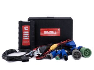
Gather any other information that are relevant, such as Fault Codes and Symptoms (eg. white smoke from exhaust). Use Cummins Insite, TEXA, a Universal Tool or a cheap Handheld Tool to read the Fault Codes.
Analyze the gathered information to find your direction and determine the Circuit with the problem.
We typically have 4 main sensor categories:
(click to go directly to that point in the post)
I’ll try to summarize the steps to follow for each sensor category.
I would suggest that you seek professional help first and then follow my guide. I cannot be held responsible if you cause any damage on your equipment, or make the wrong decisions in replacing costly components.
Everything I describe can be found in QuickServe Online, which is the official Portal for any Cummins Manuals and Wiring Diagrams.
How to troubleshoot pressure sensor faults:
Step 1: Visual Check
Key in OFF position (no circuit power)
Is the sensor damaged or broken?
Disconnect the sensor and inspect sensor and connector pins/sockets:
- Broken or bent pins?
- Pushed back pins?
- Loose connections?
- Water/moisture inside?
- Corrosion?
Replace the relevant component (sensor or connector / connector pins) if any pins are broken or loose.
Dry the pins if moisture is found. Electrical Contact Cleaner works wonders! You could use a Heat Gun, but I would avoid it, because you can damage the wires or connector if you are not careful.
If you found no damage, continue to Step 2.
Step 2: Supply Voltage Check
Having reliable tools pays off. Quality Multimeters such as the Fluke 117 or the Cojali JT2003 (this one is IP65 Certified and quite durable) will always provide accurate results.
Turn the Key in the ON position (sensor circuit with power)
Use a Wiring Diagram to find the SUPPLY and RETURN wire.
QuickServe Online (QSOL) has a FREE Wiring diagram. You only need to create an account. Follow my guide or enroll on my Online Course to become a QSOL expert.
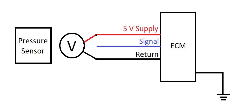
Measure the Supply Voltage between SUPPLY and RETURN at the sensor’s plug. It should be around 5 Volts. If not, ensure your Key is ON first.
Be careful not to damage the connector sockets – do not force the round multimeter probes in the sockets to get a good connection! Use a diagnostic kit with various terminals for voltage measurements.
If the Voltage at the Sensor connector is around 5 Volts, continue to Step 3, otherwise keep reading.
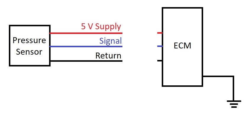
If there is still no voltage, check the supply voltage directly at the pins at the ECM. Key OFF first, disconnect the ECM connector which carries the relevant sensor wires, turn the Key ON and carefully measure the Supply voltage directly at the SUPPLY and RETURN pins at the ECM.
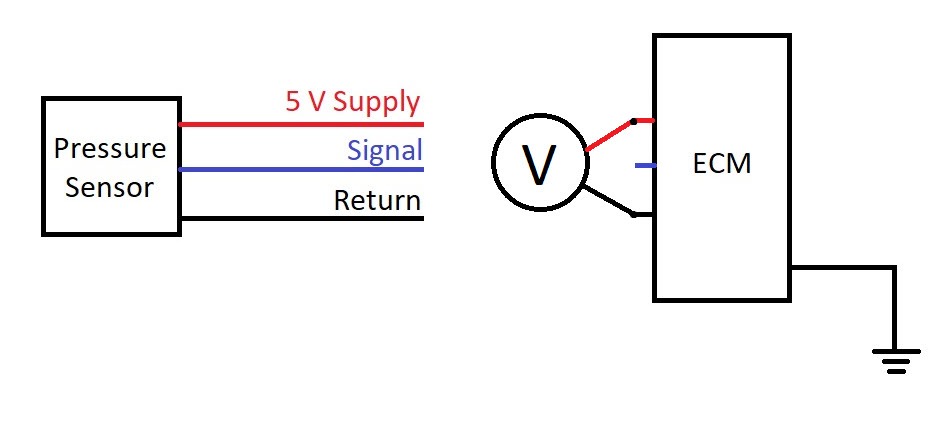
If you measured 0 Volts at the ECM (and the Key was ON!), then there is most likely an internal circuitry problem and you’ll probably have to change the ECM…
If you measured 5 Volts at the ECM, then the problem lies in the wiring. Check the Supply and Return wires for continuity. Anything below 10 Ohms indicates a good wire (Cummins specifications). Always check for short circuits between the wires too!
Step 3: Check circuit response by creating the opposite Fault Code
If you reached Step 3, then that means that you didn’t find any physical damage on the Sensor, Wires or Pins and that the ECM supplies 5 Volts to the sensor.
On this step we will quickly check the Signal by using a simple trick!
By creating the opposite Fault Code we can determine which component needs to be replaced. Keep reading to understand what I mean.
If the original Fault description is “Voltage above Normal” (pressure sensor):
That means that the signal the ECM receives, is above the Maximum allowed value.
This maximum allowed limit is 4,5 Volts on older ECMs (engine with no Aftertreatment) and 4,75 Volts on newer ECMs (with Aftertreatment).
With Key at the OFF position, disconnect the sensor. Then turn the Key ON.
Check the Fault Codes by using a diagnostic tool.
If you got a new Fault Code with description “Voltage below Normal”, then the sensor was damaged internally (short circuit from 5V to Signal).
Try that one more time and monitor the response with your diagnostic tool.
Sensor connected = “Voltage above Normal”
Sensor disconnected = “Voltage below Normal” (opposite Fault Code)
If that happens, change the sensor.
If the Fault Code did not change after you disconnected the sensor, Key OFF, disconnect the ECM harness at the ECM and Key ON again.
Read the Fault Codes with your diagnostic tool. Ignore the other newly generated Fault Codes.
If the Fault Code changed from “Voltage above Normal” to “Voltage below Normal”, the ECM is OK and the problem is somewhere in the harness. Perform continuity check on the Signal wire and Check for Short circuit between Signal and Supply wires.
Repair or Replace the wiring harness as necessary.
If the Fault Code did not change after you disconnected the wiring harness at the ECM, you probably have to change the ECM.
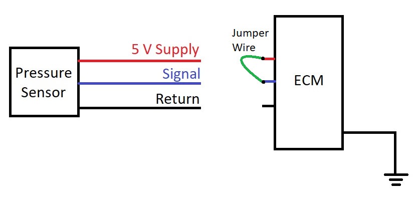
If the original Fault description is “Voltage below Normal” (pressure sensor):
Try to generate the opposite Fault Code by placing a jumper wire between the SIGNAL and RETURN pins on the sensor connector.
Key OFF and disconnect the sensor connector.
Place the jumper wire, Key ON and check the Fault Codes.
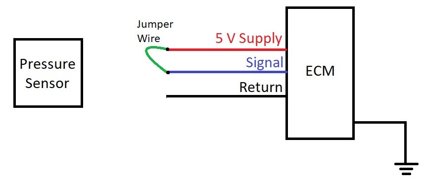
If the Fault Code changed to “Voltage above Normal”, then the wiring harness and ECM are OK. Replace the Temperature sensor.
If the Fault Code hasn’t changed, then connect the jumper wire on the ECM plug at the ECM.
Key OFF and disconnect the ECM connector.
Place the jumper wire on the ECM connector, Key ON and check the Fault Codes.
If the Fault Code changed to “Voltage above Normal”, then the wiring harness has the problem. Repair or Replace Harness.
If the Fault Code remained the same, “Voltage below Normal”, then the ECM is the problem.
Step 4: Repair or replace components and check Circuit response once more
Perform the necessary repair and check the Fault Code status with your diagnostic tool.
Continue to the next Faults (if you have any), otherwise reset the Fault Codes.
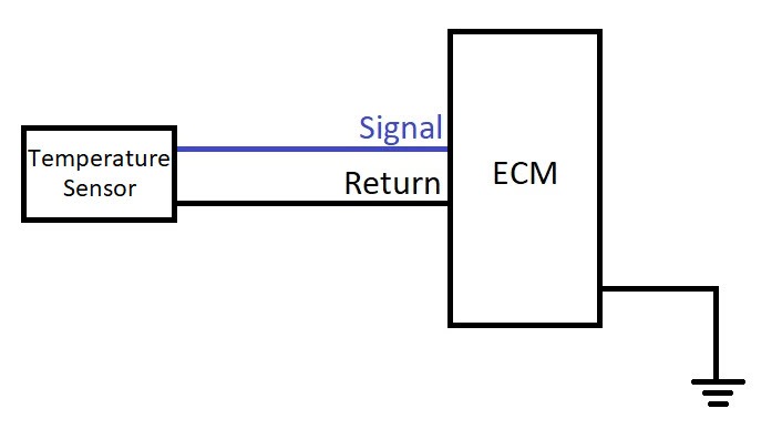
How to troubleshoot temperature sensor faults:
Step 1: Visual Check
Key in OFF position (no circuit power)
Is the sensor damaged or broken?
Disconnect the sensor and inspect sensor and connector pins/sockets:
- Broken or bent pins?
- Pushed back pins?
- Loose connections?
- Water/moisture inside?
- Corrosion?
Replace the relevant component (sensor or connector / connector pins) if any pins are broken or loose.
Dry the pins if moisture is found. Electrical Contact Cleaner works wonders! You could use a Heat Gun, but I would avoid it, because you can damage the wires or connector if you are not careful.
If you found no damage, continue to Step 2.
Step 2: Check circuit response by creating the opposite Fault Code
GOOD TO KNOW! Most of the Temperature sensors on Cummins engines, would have a resistance value between 600 to 37k Ohms.
If the original Fault description is “Voltage above Normal” (Temperature sensor):
Key OFF first and disconnect the sensor.
Find a wire and use it to create a “short” between SIGNAL and RETURN wires (jumper wire).
Key ON and check the Fault Codes with your diagnostic tool.
If the Fault Code changed to “Voltage below Normal”, the wiring harness and the ECM are OK. Change the sensor.
In case the Fault Code remained the same, perform the same procedure with the jumper wire, but on the ECM side.
Key OFF, disconnect the ECM connector.
Place the jumper wire on the SIGNAL and RETURN pins on the ECM.
Key ON and check the Fault Codes.
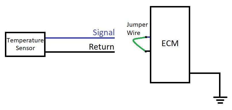
If the Fault Code changed to “Voltage below Normal”, then the problem is on the wiring harness.
Check the wiring for continuity and short circuits. Repair or replace Harness as necessary.
Check everything again if the Fault Code is still “Voltage above normal” with the jumper wire on the ECM side. Check if the pins you identified are correct, if the jumper wire is OK, etc. If you are 100% sure you did everything correctly and the fault code is still the same, then the ECM should be the problem.
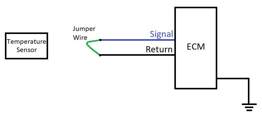
If the original Fault description is “Voltage below Normal” (Temperature sensor):
Key OFF and disconnect the sensor. Then Key ON.
If the Fault Code has changed to “Voltage above Normal”, then the sensor was damaged with an internal short circuit. Replace the sensor.
In case the Fault Code hasn’t changed, disconnect the relevant ECM connector at the ECM. Check the wiring diagram for exact information on which plug that is. (QuickServe Online!)
If the Fault Code changed to “Voltage above Normal”, the ECM is OK, but you’ll have to check the wiring harness. Check the wires for continuity and short circuit.
When the Fault Code remains the same, “Voltage below Normal”, even with the ECM connector disconnected, replace the ECM.
Step 3: Repair or replace components and check Circuit response once more
Perform the necessary repair and check the Fault Code status with your diagnostic tool.
Continue to the next Faults (if you have any), otherwise reset the Fault Codes.
Hot to troubleshoot Inductive speed sensor faults:
Inductive sensors are quite simple in their construction. It is simply a piece of wire wrapped around a magnet. Sometimes, as failsafe, they have two wires!
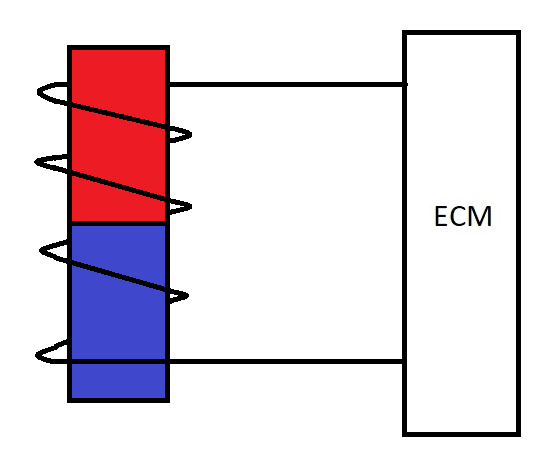
Basically, if you have an inductive sensor with only one wire, it will have two pins (one for each end of the wire) and if you have a sensor with two wires, it will have four pins in total.
There are 4 basic requirements for the sensor to be able to generate a signal:
- The sensor must not have physical damage (broken sensor, pins etc)
- The internal sensor wires must have continuity and correct resistance (no open circuit, no short circuit between coils, or unusually high resistance – check manufacturer specifications)
- The distance from the rotating part must be OK (too close and there is a risk of contact and damage, too far away and no signal will be generated)
- This is circuit related – the cables connecting the sensor to the ECM must be OK (no open or short circuit)
Typical Fault Code descriptions for Inductive sensor related problems will be “Data Erratic, Intermittent, or Incorrect”. Sometimes the ECM can also report the following two Faults: “Data Valid But Above Normal Operating Range” and “Data Valid But Below Normal Operating Range”.
Step 1: Visual Check
Key in OFF position (no circuit power)
Is the sensor damaged or broken?
Disconnect the sensor and inspect sensor and connector pins/sockets:
- Broken or bent pins?
- Pushed back pins?
- Loose connections?
- Water/moisture inside?
- Corrosion?
Replace the relevant component (sensor or connector / connector pins) if any pins are broken or loose.
Dry the pins if moisture is found and use Electrical Contact Cleaner to clean the connector.
If you found no damage, continue to Step 2.
Step 2: Measure the coil resistance
Disconnect the sensor and measure the coil resistance. Compare against specifications.
Step 3: Check the distance from the rotating part (indicator ring or reference point)
If possible, check the air gap between sensor tip and reference point. This could be a single point or teeth, like on an indicator ring.
It is worth checking if there is corrosion on the mounting surface of the sensor, pushing ich back and increasing the air gap. Sometimes O-Rings can also cause problems if they get dislodged.
If you have to re-adjust the gap, set it up like this:
- Install the sensor until it contacts the rotating part.
- Turn it back 1/2 or 3/4 of a turn to set the air gap.
Step 4: Check the wiring harness
If you checked the sensor for damage, the air gap and internal coil resistance and are happy with their condition, then you’ll need to check the wiring harness.
Key OFF, disconnect the wiring harness from the ECM and measure for open circuit, short circuit between wires and short to ground.
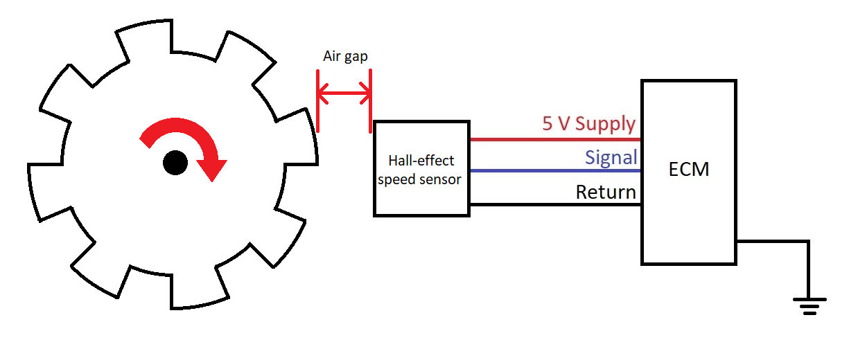
How to troubleshoot Hall-Effect sensor faults:
Typical applications of Hall-effect sensors on Cummins engines, are Engine speed sensors and Camshaft position sensors.
Some of the smaller Holset Turbochargers (ISB 4,5 engines) will also use Hall sensors to measure Turbocharger speed.
Typical Hall-sensor Fault Codes are:
- Engine Crankshaft Speed/Position – Data Erratic, Intermittent, or Incorrect
- Engine Camshaft Speed/Position Sensor – Data Erratic, Intermittent, or Incorrect
It is difficult to properly diagnose if the Hall-effect sensor itself is faulty, without using an oscilloscope.
If you do not have access to an oscilloscope, you can still effectively diagnose Hall sensor faults, by the method of elimination. It might sound complicated, but in reality, it is not. We only need to understand HOW a Hall sensor works and then it will all make sense!
How does a Hall-effect sensor work?
In 1879, Edwin Hall discovered that if a magnetic field is applied perpendicularly to a current-carrying conductor, then voltage can be measured to the sides of the conductor.
If an image is a thousand words, then the following video is a million words… Just watch it and we’ll continue from there. (Source: Wikipedia)
Let’s analyze the requirements the circuit needs to fulfil:
- There must be a current source connected (Battery, or supply voltage)
- The circuit must be in good condition, to allow current to flow (Wires = OK)
- A Voltmeter must be connected to detect the voltage at the sides (side voltage = Signal voltage)
- Look at the magnet’s distance – too far away and there is no voltage detected, like the beginning of the video (Air gap)
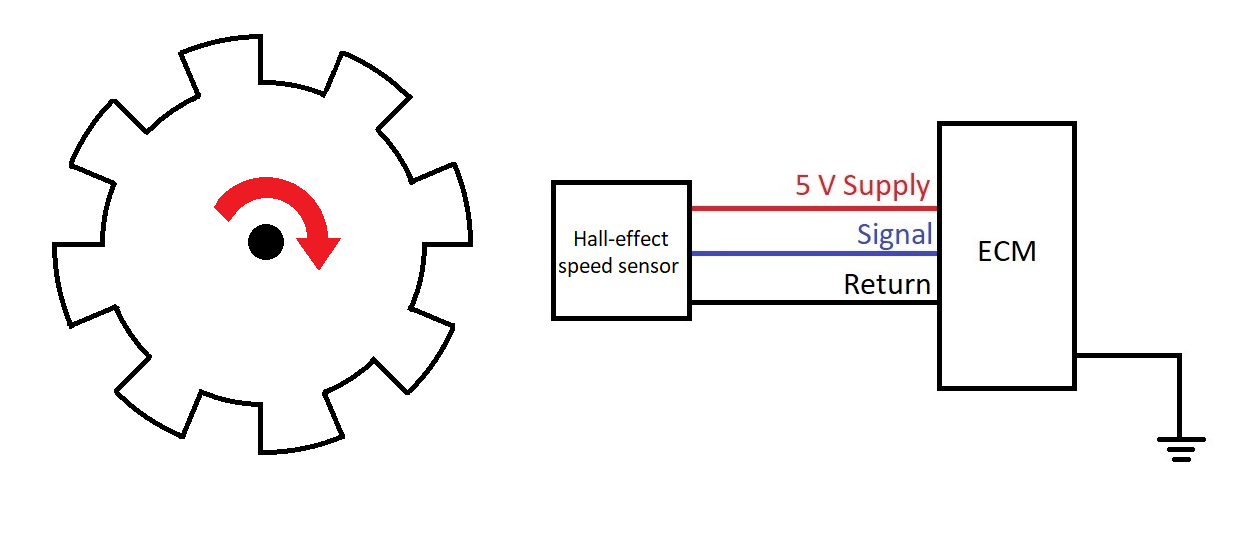
Based on the above, in order for a Hall-effect speed sensor to work, we must fulfil the following requirements on the engine’s circuit:
Step 1: Check for physical damage on the Hall sensor (Visual check)
Key in OFF position (no circuit power)
Is the sensor damaged or broken?
Disconnect the sensor and inspect sensor and connector pins/sockets:
- Broken or bent pins?
- Pushed back pins?
- Loose connections?
- Water/moisture inside?
- Corrosion?
- Inspect the sensor tip too!
Replace the relevant component (sensor or connector / connector pins) if any pins are broken or loose.
Dry the pins if moisture is found. Use Electrical Contact Cleaner to clean and protect the pins. I would avoid using a Heat Gun.
If you found no damage, continue to Step 2.
Step 2: Measure Voltage Supply
If the sensor receives no supply voltage, it cannot generate a signal.
Turn the Key in the ON position (sensor circuit with power)
Use QuickServe Online (QSOL) to find your engine’s FREE Wiring Diagram. Then identify the SUPPLY and RETURN wires.
Create your QSOL account for free! Speed up the learning curve by enrolling on my Online Course.
Measure the Supply Voltage between SUPPLY and RETURN at the sensor’s plug. It should be around 5 Volts. If not, ensure your Key is ON first.
Remember to use the correct Terminals to prevent damage on the connector pins!
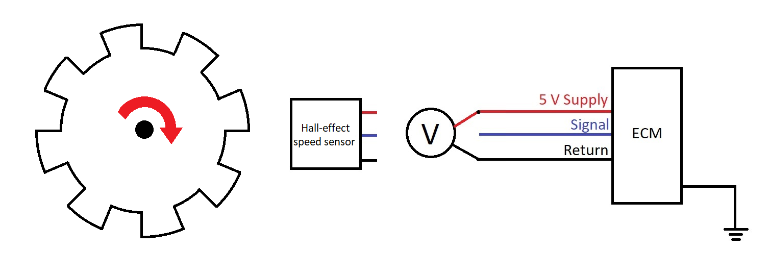
If you measured around 5 Volts supply, continue to Step 3. Otherwise, keep reading on this step.
If there is no supply present (and the Key in ON!), you’ll need to measure supply voltage on the ECM.
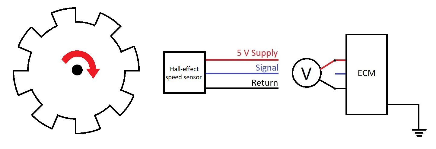
Key OFF first. Then disconnect the ECM plug.
Identify the SUPPLY and RETURN pins on the ECM connector, on the wiring diagram.
Key ON with the ECM plug disconnected and then measure sensor Supply voltage.
If the Supply is 5 Volts, the wiring harness is faulty. Perform continuity checks to verify the problem and then repair the harness.
If the Supply is NOT 5 Volts, then the ECM is faulty. Perform all the checks once more before you replace the ECM. You don’t want to make expensive mistakes!
Step 3: Check Hall Effect-sensor Signal wire
If you reached Step 3, that means the following:
- Sensor and pins have no physical damage
- The ECM supplies 5 Volts to the sensor (so it should generate a signal)
If the sensor cannot generate a Signal, then the Signal wire could be broken (open circuit), or shorted to another wire or to ground.
Perform continuity checks on the Signal wire.
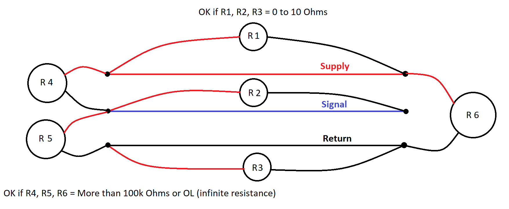
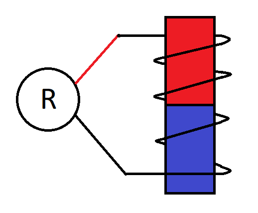
Wire Resistance should be less than 10 Ohms. (see R2 check on the image below)
Pin-to-pin check should give infinite resistance or show “OL” (Overload = Infinite) if you are using a Fluke Multimeter or similar. According to Cummins there is no short circuit if the resistance is more than 100k Ohms. (Check R4 and R5 on the image below)
If the wire has high resistance, it is broken and cannot carry the signal to the ECM. Repair or replace the wiring harness.
If the wire resistance is OK, but checks R4 and/or R5 show less than 100k Ohms, there is probably a short circuit to Return or Supply wires.
Do not forget to measure between Signal wire and Ground too! (Engine or Chassis ground, check R2 below).
Resistance should be infinite as well.
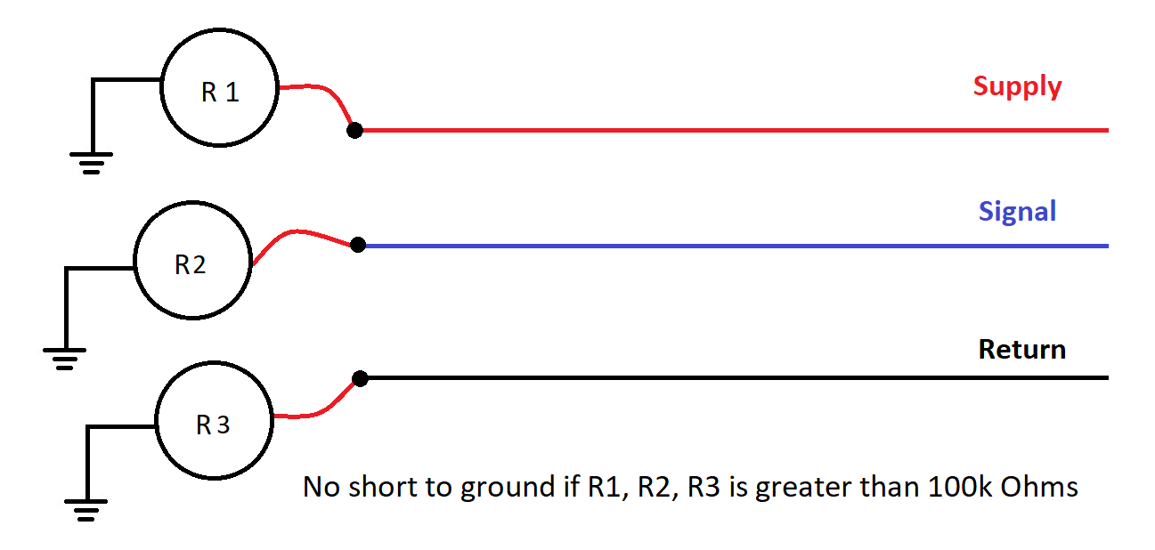
If your wires are OK – no high resistance or shorts to ground or other wires, go to Step 4.
Step 4: Measure the Air gap
So far we know:
- Sensor or connector is not broken
- Supply Voltage is OK
- Signal wire is OK
We already know that there are only 4 things to check on Hall-effect sensors (see here if you forgot them already!).
The last thing to check is the Air Gap.
Find the specifications in QuickServe Online.
Open the Service manual and navigate to:
Cylinder Block > Crankshaft Speed Indicator Ring
Sometimes you can find the information on:
Electronic Controls > Crankshaft Position Sensor OR Electronic Controls > Camshaft Position Sensor.
The Air Gap typically must be between 0.032 in to 0.060 in (0,8 mm to 1,5 mm). This might vary for your engine – ALWAYS consult the manual!
If you found the air gap to be out of specification, check the indicator ring, sensor mounting plate/position and sensor for damage.
Replace any components you found to be faulty.
Do you need training on Cummins Sensor Fault Code troubleshooting?
I can always offer a tailored training course to suit your needs. This can be a webinar made just for you or your group of technicians, or even a course at your premises.
There is also a specific section on the website with the next Live webinar dates on various topics.
Secure your webinar spot now!
Cummins Aftertreatment Systems Training Webinar – In-depth analysis of Aftertreatment System Architecture, Common Problems & Solutions.
Cummins QuickServe Online Webinar – All you need to know: from Zero to Hero.
If you prefer to learn at your own pace, have a look at my Online courses too:
Cummins QuickServe Online Fundamentals
From time to time, I upload short videos on my YouTube channel. Maybe you’ll find something interesting there!
If you have any suggestions, feedback, or requests, please feel free to contact me to discuss further!